Designing a Custom Solenoid Valve
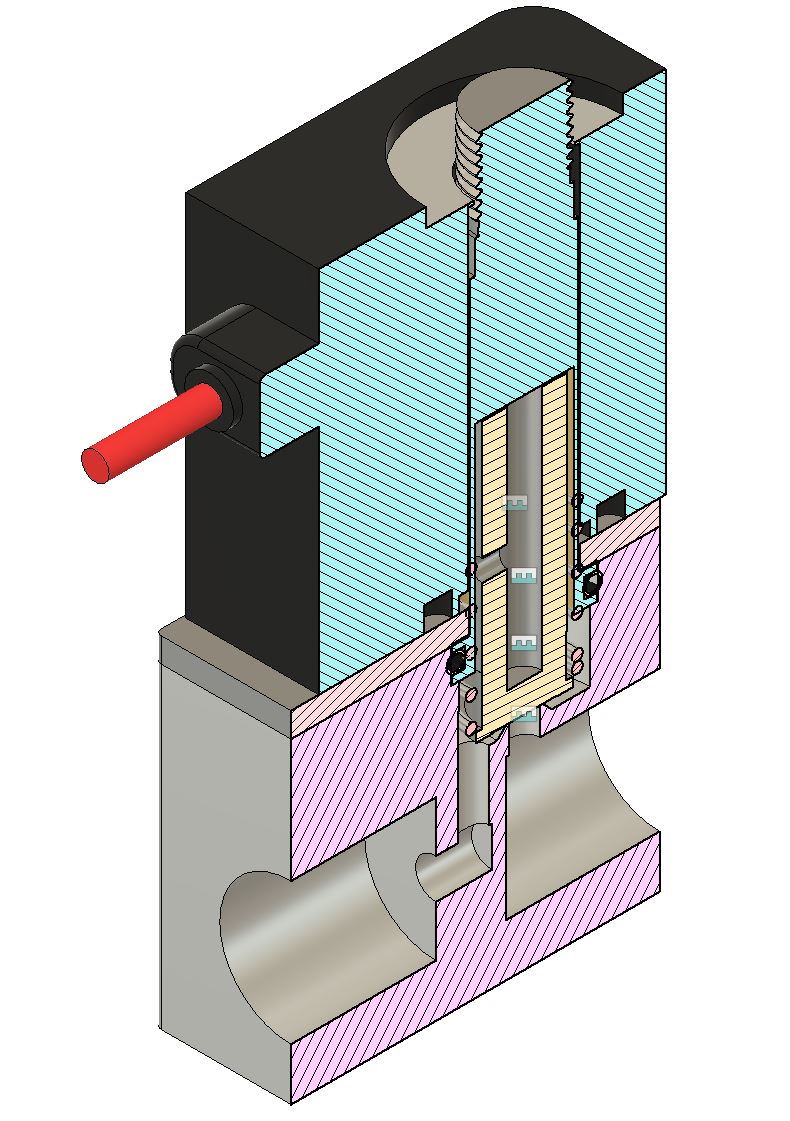
I've always wanted to design a compact miniaturized Cold Gas Reaction Control System (RCS) for rockets, but one of the trickiest part comes down to creating a light weight/form factor design just using off the shelf components. Since in a Cold Gas RCS operates by send gas through variously angled thrusters on the body of the rocket at different times based on the desired attitude of the rocket, we'd need some means of discretely controlling gas flow.
Solenoid Valves solve this need, they use a solenoid (simply a winding of wire) as a miniature electromagnet to mechanically adjust parts of a valve to control fluid flow (in most cases either as fully open to flow or completely closed off).
In this tutorial we'll go into exactly how we can design our own solenoid using mostly off the shelf components and a 3D Printer. We'll split this up into sections:
- The Anatomy of a Basic Solenoid Valve
- Defining the Specifications of our Valve
- Designing the Coil
- Designing the Piston & Plunger
- Designing the Valve Body
- Performing Testing
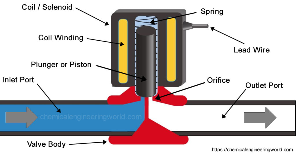
The Anatomy of a Basic Solenoid Valve
- The Coil / Solenoid
- Coil Winding: This is typically a tightly wound enamel coated copper wire that is wrapped around a ferrous core in order to create an electromagnet.
- Piston: This is a shaft that will be in the direct presence of the inner core's magnetic field created by the electromagnet, and thus have a linear up or down motion depending on how the electromagnet is designed
- Plunger: This is typically coupled directly to the piston and is made of a sealing material that will seal against the valve body, this will prevent fluid from the inlet side from moving to the outlet.
- Spring: This helps to define the de-energized state of the valve so that when the electromagnet is off the plunger is either closed or open to fluid flow.
- The Valve Body
- Inlet Port: This is typically a threaded port for a fitting to be installed onto the valve. This port is where the fluid source comes from and is upstream of the plunger. It's important to remember that not all solenoid valves can be treated as a bi-directional valve, some utilize the inlet pressure to help move the piston. Valves that do this typically will have labels on them defining the port name as Inlet or outlet.
- Outlet Port: This is also a threaded port directly downstream of the plunger.
- The Orifice: This is the location typically near where the plunger is sealing against. While solenoid valves in theory should be able to open/close fluid flow, it does have the downside of adding resistance to the flow of fluid since the area is being restricted by the valve body and plunger.
Defining Valve Specifications
All valves have various different specifications ranging from Inlet Pressure Requirements, CV, Temperature, Response Time, ect. We also need to consider our manufacturing limitations and how this will limit our ability to valves. Since in our case we only have access to a 3D Printer (specifically a Plastic FDM style) we will be limited to using fluids that the plastic will be able to support.
In my case I'm going to be designing a solenoid valve that will have 1/4" NPT Threads at their interfaces and can handle pressures between 13-120psia at near ambient temperatures. I'm not too sure what sorts of CV values/response times I'll be able to achieve so I leave that spec open, these will be hard to know until I build something.
- Port Size: This is the size of the connection port found at the inlet and outlet ports.
- Pressure: While specification can typically be met by simply increasing the thickness of our valve body channels, we seriously need to exercise extreme caution when operating our valve. 3D Printed parts do not have constant material properties as we'd like to just consider them to be solid chunks of plastic. In reality, the way that the layers are formed lead to non-homogenous structural properties throughout the material. This can easily lead the plastic to shatter if the pressures are excessive. Parts can also experience fatigue over time just from pressure cycling causing each iteration of part usage to shorten the lifetime of the valve before it fails. We will attempt to alleviate these concerns by using excessively high safety factors and by exercising extreme caution and protection during testing.
- Temperature: There are various forms of plastics that can be used for FDM 3D printing, seek the specifications of the filament to get a better idea of the temperature ranges of the plastic. Be careful in working on the upper or lower bounds of a plastic's temperature ranges.
- CV: Also known as flow coefficient defines the flow capacity of a valve under specific conditions. While CV itself is dimensionless, it relates how much flow of the fluid can go through the valve at a given inlet and outlet pressure. This will be critical in designing a valve for an Cold Gas RCS thruster since for a thruster to achieve the desired thrust it will require a desired fluid flow rate. If the fluid flow rate is too high and the Valve's CV is too low, the valve will prevent the thruster from achieving the desired thrust.
- Response Time: This is the amount of time it takes for the valve to go from fully open to fully closed and vice versa. Since we are limited in our ability to create tight tolerance parts and in modifying metal off the shelf parts, it will be inevitable that plastic friction and wear and cause our valve performance to be subpar and degrade over time. This will either take the form of leak through the plunger from the inlet to the outlet side or by increasing the time it takes for the plunger to react. Since the plunger is also going to be in the presence of the fluid, the pressure exerted on the plunger may also cause the shaft to bind or seize, decreasing valve response time.
In my case I'm going to be designing a solenoid valve that will have 1/4" NPT Threads at their interfaces and can handle pressures between 13-120psia at near ambient temperatures. I'm not too sure what sorts of CV values/response times I'll be able to achieve so I leave that spec open, these will be hard to know until I build something.
Designing the Coil (Equation Approach)
When most people start to design a coil for the purposes of a solenoid/electromagnet they attempt to use the equations I provide below. While this might provide a rough order of magnitude in terms of what the strength of the magnetic field in the coil will be, it will not be very accurate. This is because in reality there are so many factors that will impact the field strength at any given point.
A few drawbacks of the equation:
For this reason, we will begin by using these equations, but then moving to a simulation software for better verification before physically making a coil and performing some tests.
A few drawbacks of the equation:
- The equation assumes a constant magnetic field throughout the length of the coil (the B vector magnitudes within the field inside the coil are equal at all points). This is not true in reality, the B vectors will vary in magnitude across the length of the coil.
- In almost all cases the relative permittivity values are going to be inaccurate, this is just because the geometry of the core is assumed to be a complete solid (which is not the case for a solenoid which will have a hole in the center for the plunger to move through). But also some core materials do not have constant permittivity values, they are constantly changing with regard to the magnetic field generated through the core. Also any conducting material near the coil is going to play some role in how the magnetic field behaves.
- The equation does not take into account core material saturation. The equations led us to believe that even if I continue to add more winds or current to my coil I can achieve an unbounded magnetic field strength. However, this is not the case. All core materials have a maximum field strength that they will saturate at and will not allow for higher strength.
For this reason, we will begin by using these equations, but then moving to a simulation software for better verification before physically making a coil and performing some tests.
- B = "Magnetic Flux Density". This is the strength of the magnetic field at a particular point in space. [Teslas]
- μ0 = "Magnetic Constant" = 1.257 x 10^-6 [m kg s^-2 A^-2]
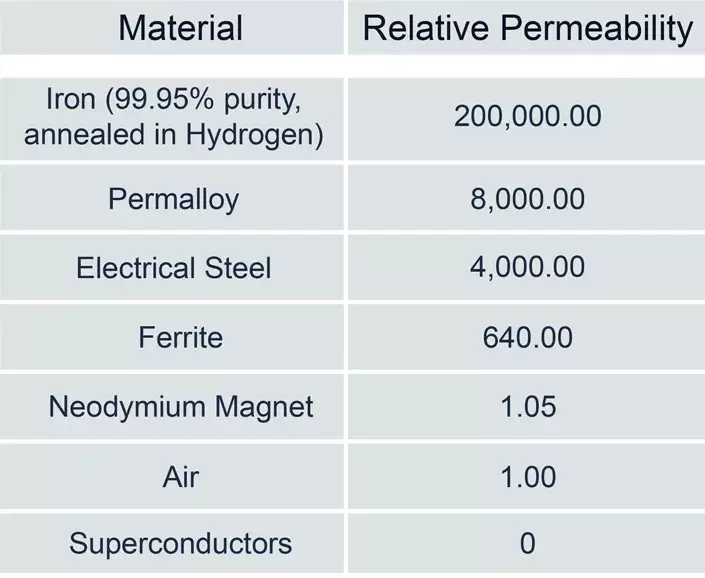
- μr = "Core Relative Permittivity" = [SEE TABLE BELOW]
- N = Number of Coil Windings
- ɪ = Current flowing through the Coil [Amps]
- l = Length of the Core [Meters]
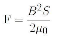
We now can use the equation to help us to calculate the force exerted on a magnetic object within a magnetic field:
We've already talked about B & μ0.
- F = Electromagnetic Force experienced by the Plunger
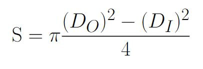
- S = Cross Sectional Area of the Coil
- D0 = Coil Outer Diameter
- DI = Coil Inner Diameter
Designing the Coil (Simulation Approach)
For more accurate Magnetic Field Strength values we can use a 2D Magnetic Finite Element Solver such as FEMM 4.2.You'll quickly realize how obsolete FEMM's user interface is, especially when adding points and lines manually. Which is why it is much simpler to import a DXF File. I will be starting with a 3D CAD Model of a reference solenoid valve (modeled off of this generic Amazon Solenoid Valve)
Step #1: Create a new Magnetics Problem
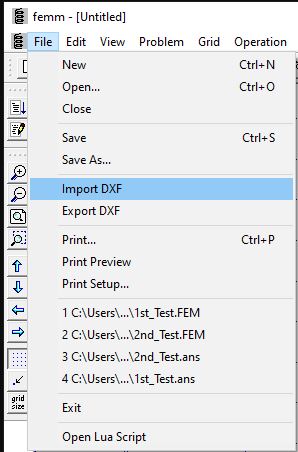
Step #2: Import the following DXF
| coil_plunger_profile.dxf | |
| File Size: | 14 kb |
| File Type: | dxf |
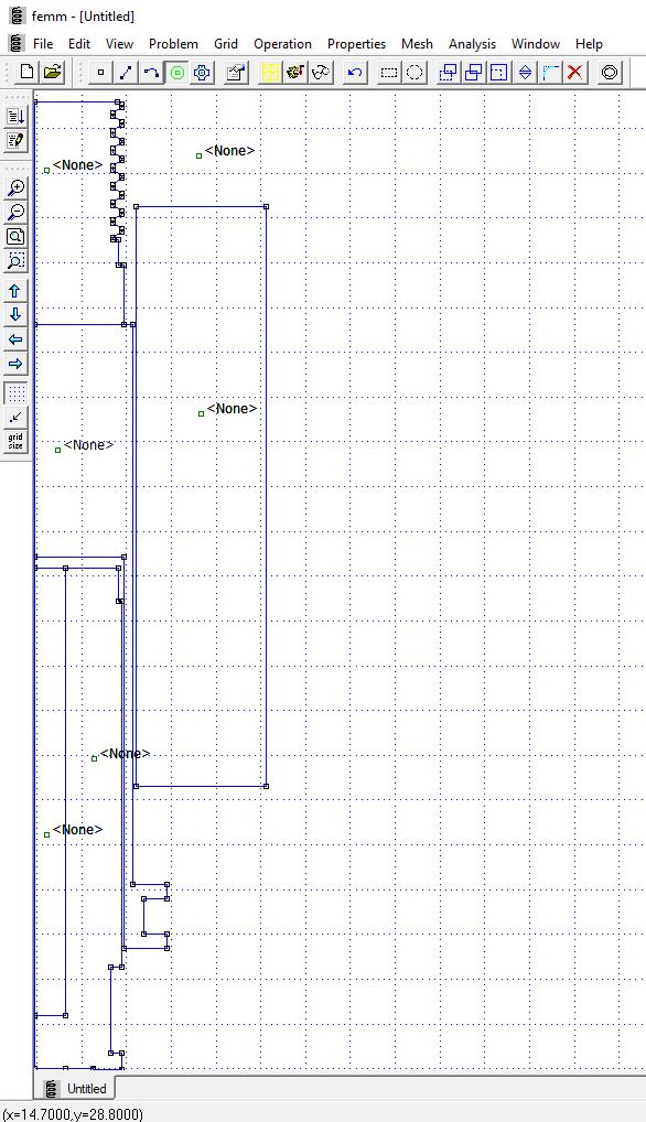
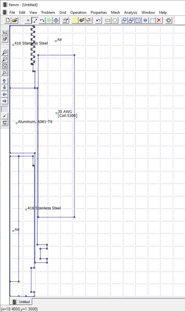
Step #3: Define Property Nodes as seen in the picture below (Use the Green circle Icon on the top bar before clicking on the various points)
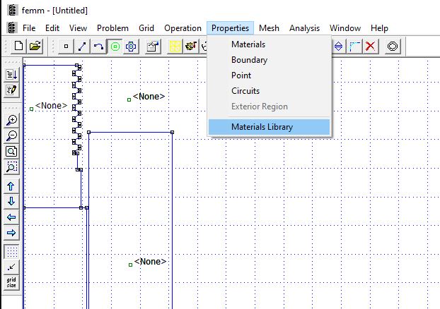
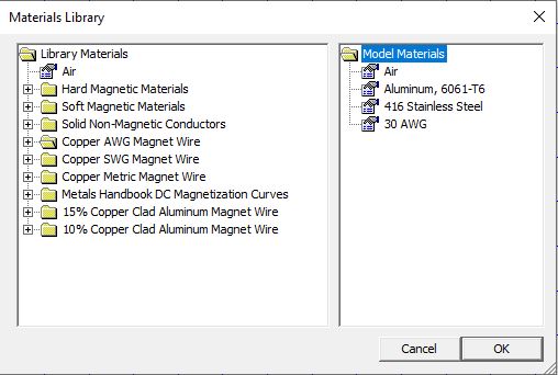
Step #4: Navigate to the Materials Library & Add the Following Materials
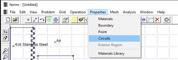
Step #5: Navigate to Properties > Circuits and add the following circuit details of the coil:
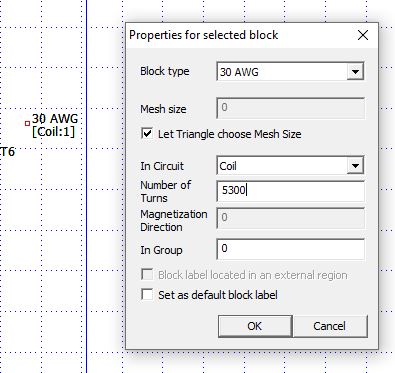
Step #6: Right click on each of the Added Property Node, then click the Property Selector Tool, Set the block types as seen below for each node:
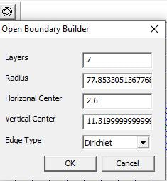
Step#7: Verify Correct Boundary Conditions
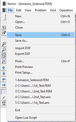
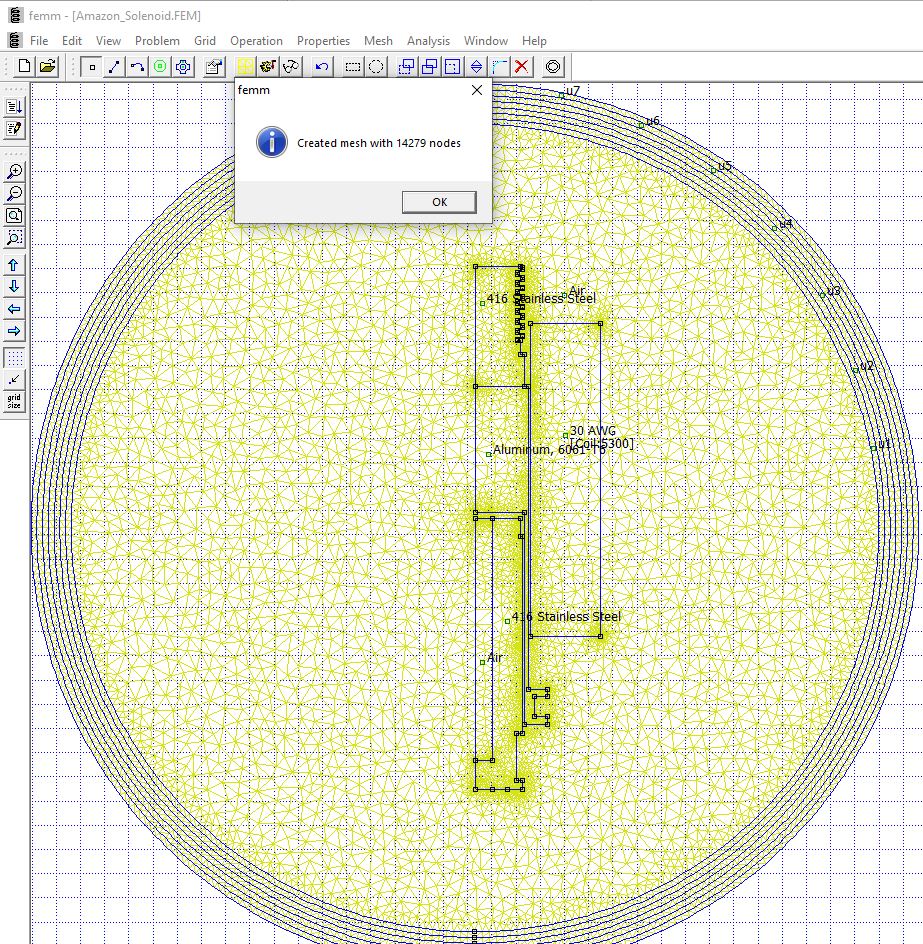
Step#8: Save the File & Click on the Toolbar button with Yellow Mesh
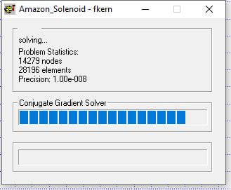
Step #9: Click the "Turn the Crank" button on the Toolbar (You should see a loading bar quickly pop up and disappear
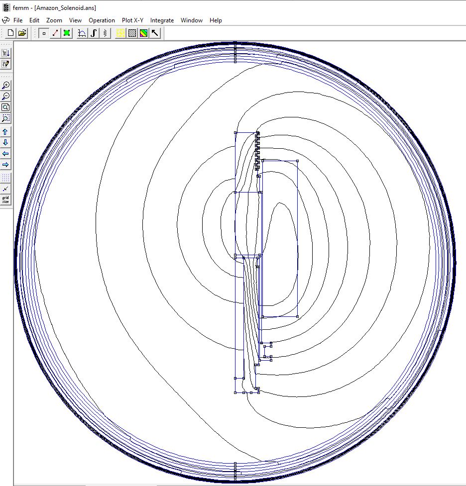
Step #10: Click on the Glasses icon on the Toolbar to Analyze the results
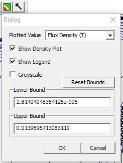
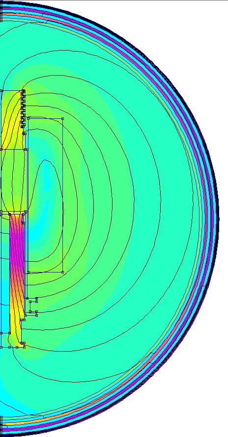
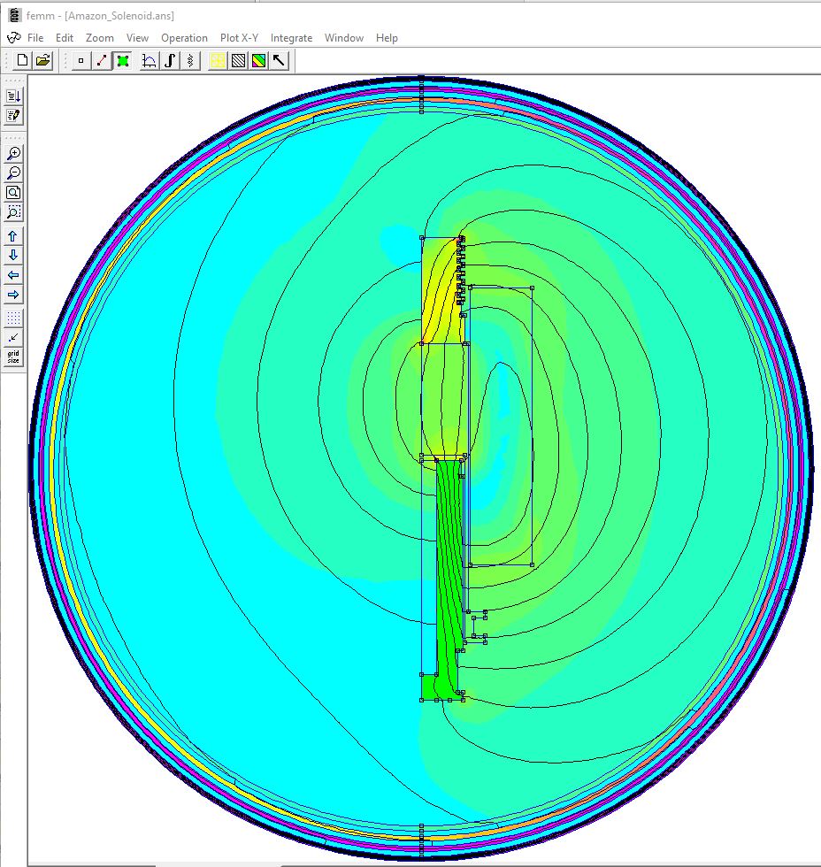
Step #11: Click on the Red/Yellow/Green Icon on the Tool Bar and select the settings as below:
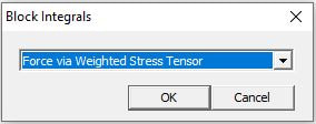
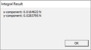
Step #12: Click on the Green Box Icon on the Tool bar, then click on the Plunger (it should turn green), Click the Integral Button on the Toolbar, Select "Force via Weighted Stress Tensor"
