COPV Burst Stand
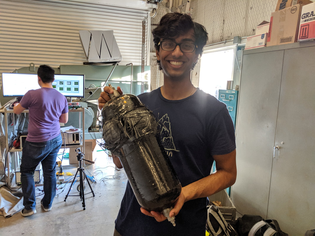
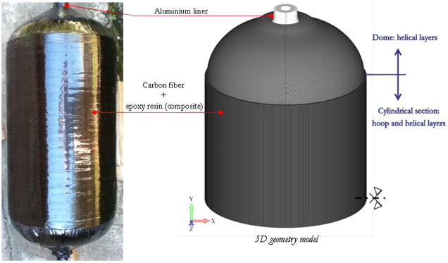
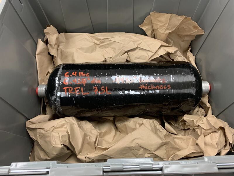
One of the projects that I worked on for the Texas Rocket Engineering Lab (TREL) was for a Composite Overlay Pressure Vessel (COPV) hydro-static test bench. This stand was designed to test and validate the carbon fiber winding patterns of our COPV Tanks. These tanks will be used to hold our propellants and are subject to containing high pressure liquids (in our case LOX/RP1). The ability to test the structural integrity of tanks, as mentioned before these COPV tanks are special in that they are made of a relatively thin layer of aluminum surrounded multiple layers of winded carbon fiber strands, as seen in Figure 1-1.
TREL is manufacturing their tanks by taking Industrial propellant tanks provided by -------, and having Firefly Aerospace follow a specific winding pattern as specified by TREL. The output from Firefly will then be our COPV Tank. However, unlike other commercially available tanks, data will not be provided in terms of the tested stress/strain data of the tank when subjected to a specified pressure value. This testing will need to be performed by TREL's TLO team.
Brief Overview on our Test setup
Using a hydrostatic test system which takes in compressed air(120psi) and a water inlet from a hose, it is able to pressurize the test system to around 6,000 psi by using water. Naturally you might think to test your system with the fluid that will be used during flight, but this setup poses to many hazards, especially when the tank ruptures. Water however, will be able to absorb the energy caused by the tank rupturing much better than any other liquid/gas.
By placing a series of strain gauges along the exterior of the tank we will be able to measure the hoop stress and axial stress of the tank. We will measure this strain data from an empty tank up to the maximum operating pressure with a margin for safety factor.
Main Deliverables from this test:
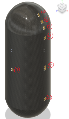
- Axial and Longitudinal stress on the tank at 7 points on the tank.
Electrical Test setup
The Electrical interface to the tank began with laying out positions on the tank where the structures team would like to acquire strain data from. Strain gauge locations were selected to all be in line and measure both the hoop and axial strain. Some gauges were selected to be positioned on the junction from the cylindrical portion of the tank to the dome part of the tank to measure any stress concentration.
|
|
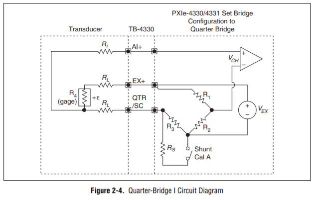
We selected multiple bi-axial strain gauges to conserve the individual number of strain gauges needed to be applied to the surface of the tank. Originally we had selected the strain gauges to be in a half bridge configuration for temperature compensation when out at the pad. However, the problem with this approach was that the dummy resistor would be experience loading and not just the same temperature. This would cause the calculations for the strain in that direction to be off. For this reason we selected a quarter bridge circuit to measure the single axis of the strain gauges.
|

Stain gauges would be measuring strain from Hoop stress and Axial stress
|
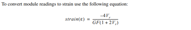
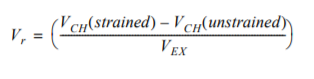
An excitation of 10V was selected since this was the maximum voltage that the Bridge Compensation Module (NI PXIe-4330) and each strain gauge had a maximum input voltage rating of 13V. From the equations listed above we could back out what the strain at that point was on the surface of the tank. Each strain guage had a resistance of 350 ohms (GF: 2.03) and with no load maintained a balanced bridge with a offset of 0.0005V as detected by our ADC.
Manufacturing & Integration
Integration began with applying the strain gauges to the surface of our COPV tank. We began by sanding away at the surface of the tank as to roughen up the surface and allow us to properly bond the gauge to the surface. After sanding, we thoroughly cleaned the surface with isopropyl alcohol. Once cleaned we applied a small amount of Cyanoacrylate to the back of the strain gauge and pressed it to the surface to be bonded. The whole process of bonding each of the strain gauges and soldering them to a wiring harness took around 5 hours. Once interfaced with the bridge compensation module we verified that the gauges reacted to strain performed on a test article.
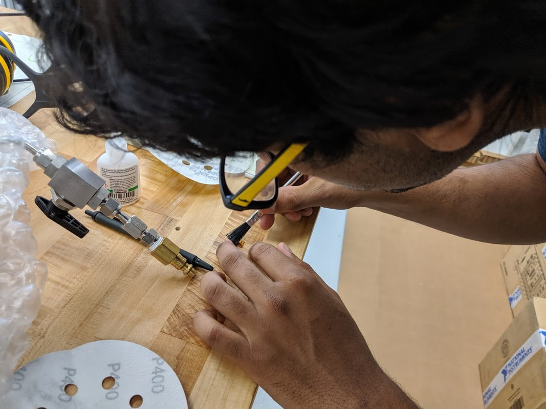
Applying CA to the bottom surface of the strain gauge
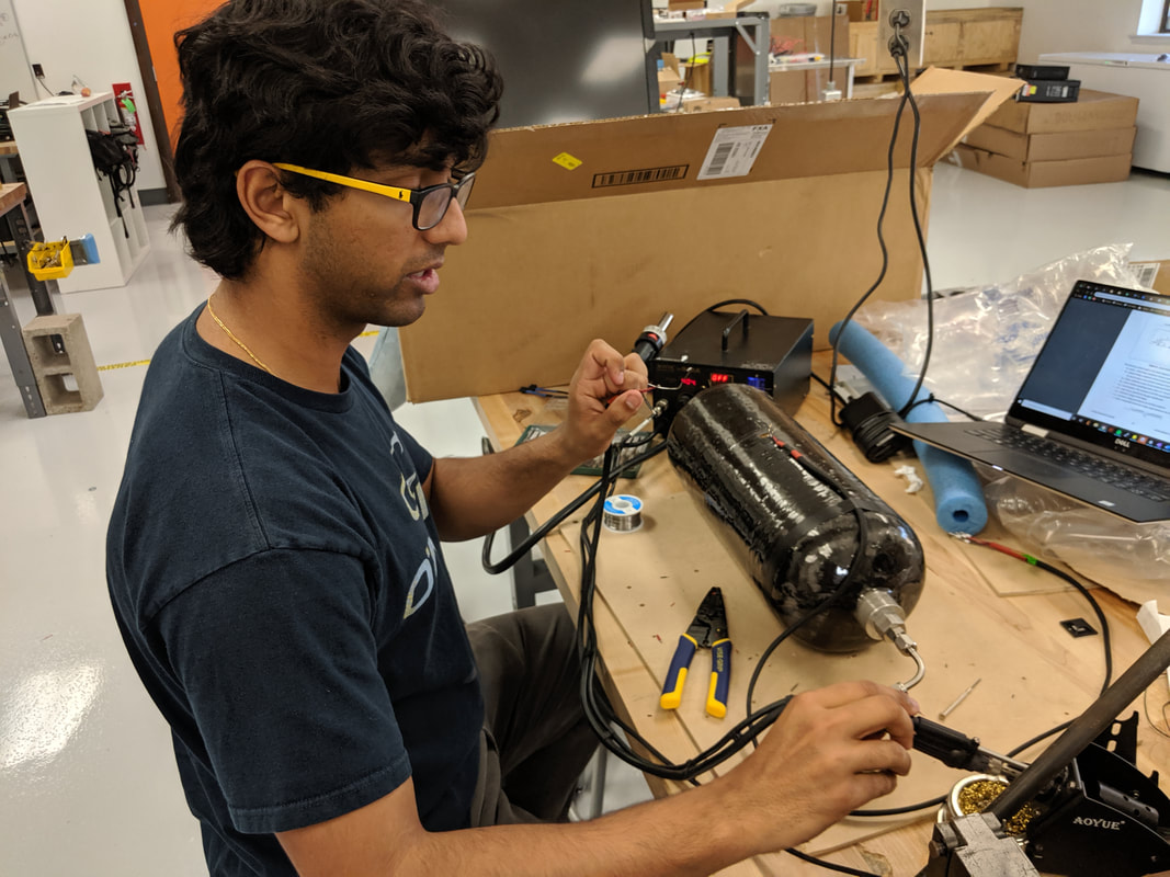
Mounting a single harnessing cable to the COPV
|

Application process of the strain gauges onto the surface of the COPV
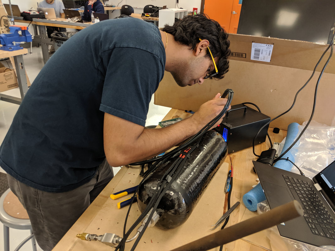
Finishing up the last of the harnessing to the COPV
|
Testing
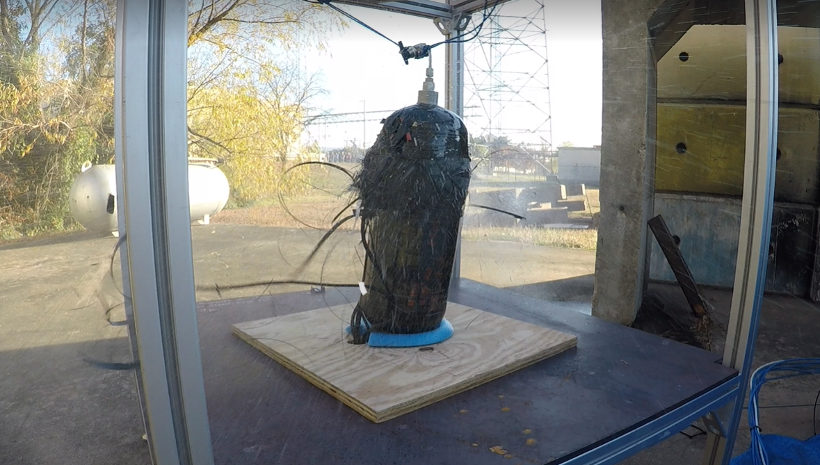
The COPV Burst test was conducted at Pickle Research Campus (PRC) at the LRA hybrid engine test pad. Many of the electrical interfaces that LRA utilized for their electrical system would also be used for this test. As lead of Electrical interfaces and Camera man, I was responsible to assessing the working status of all electrical interfaces to the test article as well as monitoring the camera equipment.
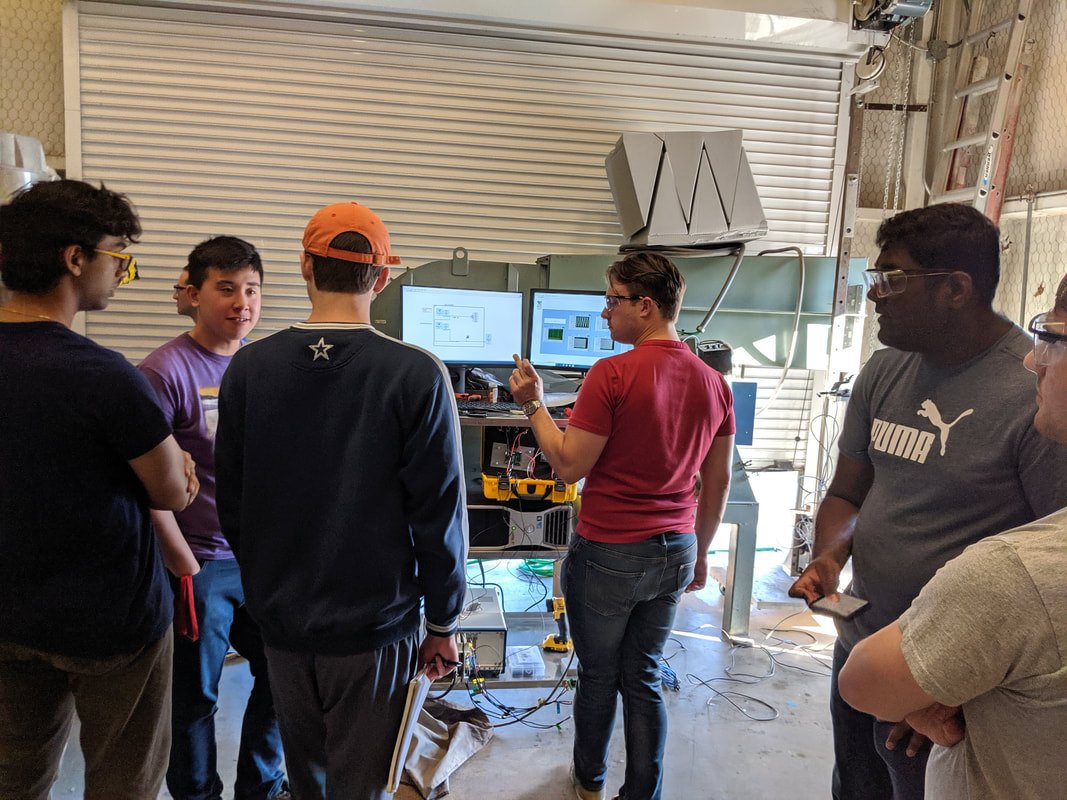
Pictures from the Control Room