Resistor Circuit Analysis
One of the most fundamental circuit diagrams you will see all over the place in electrical engineering are resistor circuits. The reason these are so important is because they are so easily able to show how exactly current will flow through a system. The analysis we will be performing on these circuits are gonna be pretty simple. Just finding the Voltage, Current at certain parts of the circuit, and maybe a bit of power consumption from specific resistors.
What are Resistors and why are they important?
The best way the explain how a resistor works is to relate it to how water flows through a pipe. So far from what we have learned, you can image the water pressure in a line to be the voltage potential, and you will notice that as you have a water pressure difference in the line, the water will want to move from high pressure to low pressure (similarly to how conventional current flow states that current moves from high voltage potentials to low voltage potentials). Current though a resistor works similarly to how water moves though a constricted pipe. By constricting the pipe (think of wires as large pipes that electrons can travel though)we effectively can limit the current flow. Think of it like this:

Notice what is happening in the figure. The voltage is what is responsible for driving the electrons though the pipe, the resistance (which is measured in ohms) "resists" the flow of electrons through the pipe. You can think of the current as a mass flow rate though a pipe, and that resistors are like orifices that can restrict the mass flow rate. However, as we know in real life orifices do restrict the mass flow rate, but they also create pressure drops in pipes. Similarly, we will notice that resistors will create a voltage drop from one end of the resistor to the other.
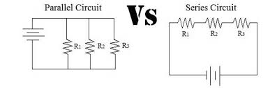
Ok, now that we get the gist of what resistors are capable of we need to get familiar with analyzing circuits with multiple resistors! One thing we should probably get out of the way first is the difference between series circuits and parallel circuits. It is kinda difficult to explain how these two types of layouts look like, but here is a good diagram to follow to get an idea of what series and parallel look like:
Ok, now that we get the gist of what resistors are capable of we need to get familiar with analyzing circuits with multiple resistors! One thing we should probably get out of the way first is the difference between series circuits and parallel circuits. It is kinda difficult to explain how these two types of layouts look like, but here is a good diagram to follow to get an idea of what series and parallel look like:
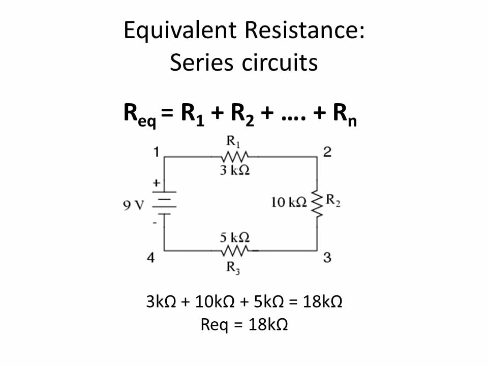
Resistors in Series
So one thing that is really gonna make our lives easy is with spotting resistors that are either in series or in parallel since we can simplify them into a single resistor. If you ever see resistors that are in series with one another you can create a single equivalent resistor by adding up each resistor in series. Here is a good picture to follow:
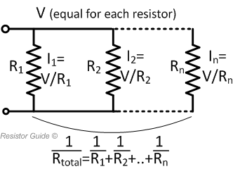
Resistors in Parallel
Unlike resistors in series, finding the equivalent resistance of parallel resistors is a bit different, but you can just follow this formula:
Resistors in Combination
Keep in mind that resistors can be put in both series and in parallel at the same time, here is a great example:
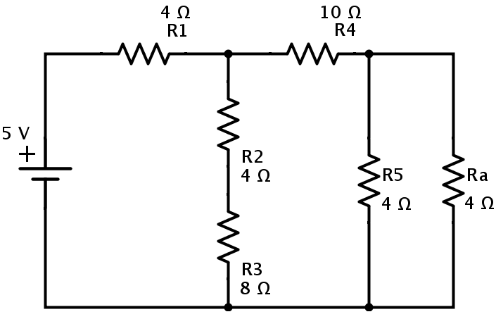
Ok, let's walk though this step by step! Notice that R2 and R3 are in series which means we can make one big resistor out of those two. Then notice that R5 and Ra are in parallel and will combine to a single resistor that will then be in series with R4 so we can add that. Then once we have added R4 with the R5 and Ra parallel resistors that will then we in parallel with the series resistor of R2 and R3. And finally that whole simplification will be in series with R1 and can just be added to make a single resistor in series with the 5V source.
Actual Resistor Circuit Analysis
All circuit analysis is based off of 3 simple governing law/rules. The first is Ohm's Law which defines the relation between resistance, voltage, and current (OHM'S LAW IS ONLY VALID FOR LINEAR COMPONENTS LIKE RESISTORS). The second two rules are Kirchhoff's Current Law and Kirchhoff's Voltage Law.
Kirchhoff's Current Law is defined at nodes within a circuit. Let's take a look at what we consider to be nodes in a circuit:
Kirchhoff's Current Law is defined at nodes within a circuit. Let's take a look at what we consider to be nodes in a circuit:
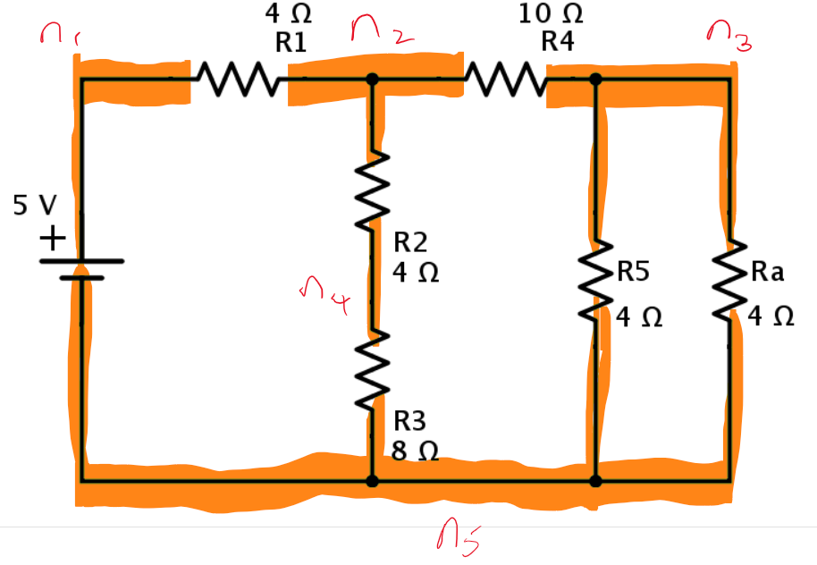
In the circuit diagram shown above, there exists 5 nodes. Although they are called nodes the whole collection of lines that are connect together make up all the same node. Kirchhoff's Current rule states that the amount of current going into a node must equal the amount of current exiting the node. This is pretty much conservation of energy, the energy that enters the system must equal the amount that leaves the system.
Kirchhoff's Voltage Law is defined within a closed loop in a circuit. Any loop within a circuit must follow this condition, that the summation of all of the voltage increases and decreases should equal zero within a full loop as seen below:
Now Let's Put it all together!
Real World Applications
Now you might be thinking, "Ok, well that's nice I essentially have a way to restrict the current flow, so what?". Well this has lots of applications, but the two most prominently utilized resistors are either for limiting current to power sensitive electronics or to utilize that concept we talked about before (the fact that resistors create a voltage drop).
Current Limiting Resistors
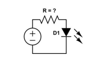
Now you may be thinking "Why did we just call it a current limiting resistor, isn't that redundant for what a resistor does??" and you would be correct, but this title what we call a certain configuration that resistors are placed, to which they will limit the current to feed into another device. The way we do this is super simple, just put the resistor in front of the device we want to connect to. The specific example we are gonna look at is super relevant, and it is used to power LEDs (Light Emitting Diode) without totally destroying them. We haven't really talked too much about diodes, and I'll save that for another page, but for now just think of them as one way check valves in a pipe (they only allow current to flow in one direction). But the special thing of LEDs is not only that they are diodes, but also they emit a light when operated at a specific voltage and current. The main take away about all diodes though, is that they effectively have zero resistance, this is a problem when it comes to Ohm's Law, if I = V/R, since R= 0 ohms as the limit of I approaches infinity, the current going thought the LED will attempt to become infinity, but in LED will generally burn out at around 500 mAmps before that can happen.
This is why you cannot simply hook up an LED to a battery, you will destroy it this way. The proper way to power an LED is through the use of a "current limiting resistor" to be put in series with the LED similarly to this:
This is why you cannot simply hook up an LED to a battery, you will destroy it this way. The proper way to power an LED is through the use of a "current limiting resistor" to be put in series with the LED similarly to this: