Project Quasar: A Custom DAQ soulution
One thing that limits many amateur rocketry teams from being able to conduct testing of custom designed rocket engines is cost of electronic instrumentation. This electronic instrumentation is used to be able to properly allocate data from any sort of testing needed to be performed. National Instruments (NI) is a well known company that provides high quality data acquisition systems but at a very steep price which can make it very hard to fund on the amateur level. Another issue with industrial solutions from companies like NI is that it shrouds the internal electronics required for data acquisition into a black box. This inhibits amateur students from being able to learn the fundamentals of how the data is electronically acquired which is key to getting accurate data. Most importantly, a project like this will give you the fundamentals to be able to design point to point communication systems that gives you a large amount of knowledge that will make you stand out to new space employers. So let's get right into it!
Some background for my implementation....
I design all of the test site electronics for the PRC (Pickle Research Center) rocket test site at the University of Texas at Austin which is supported by our amateur rocketry team LRA (Longhorn Rocketry Association). Our site has been designed to support the testing of hybrid rocket engines. We already have some NI DAQ hardware to support such testing, but given the model we have, we do not have much room to expand our Input/Outputs for sensors/control actuators if needed. Their ultimate goal is to have a system capable of almost real time communication to the site for getting data and being able to control the whole test site autonomously. For those of you who have no idea what this test stand is take a look at "Horizontal Test Stand" under my rocketry projects tab.
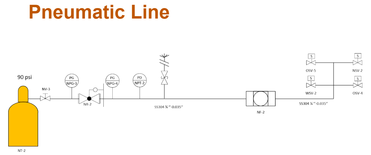
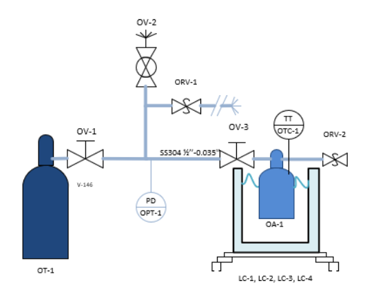
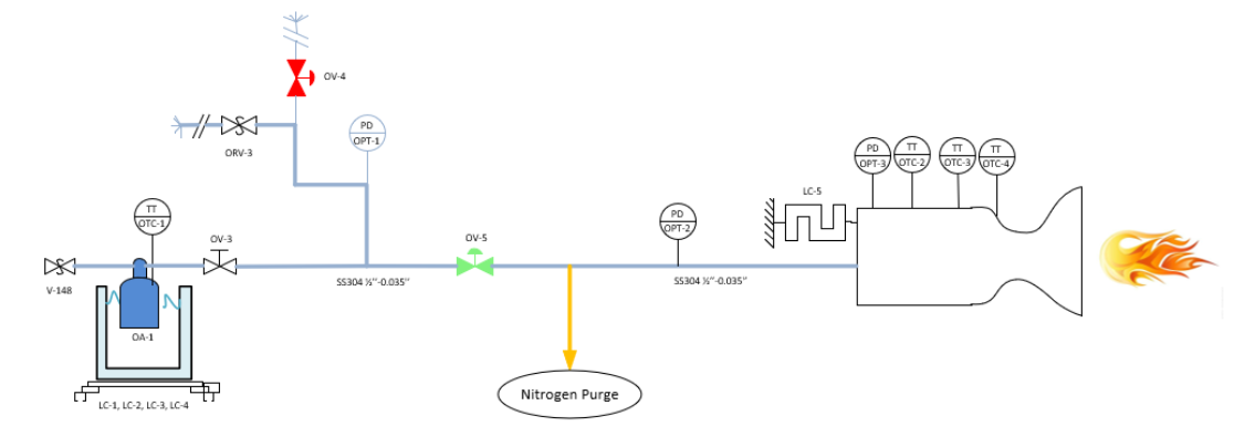
Mechanical/Fluid wise here is how our stand operates:
Mechanical/Fluid wise here is how our stand operates:
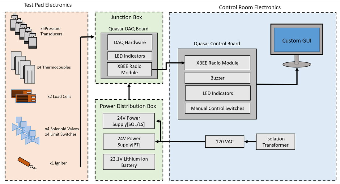
Electrical wise here is a diagram of all of the sensors on our test stand:
From this diagram you can see that we have the following instruments:
- 4 Pneumatic Solenoid Valves (Allow fluid to move throughout lines)
- Solenoid #1: Water Valve [SOL1: WSV-2]
- Solenoid #2: Oxidizer Valve 1 [SOL2: OSV-4]
- Solenoid #3: Oxidizer Valve 2 [SOL3: OSV-5]
- Solenoid #4: Nitrogen Valve [SOL 4: NSV-2]
- 4 Limit Switches (Used for mechanical/electrical feedback that the valve is in the open/closed state)
- Limit Switch #1: [LS1: WSV-2]
- Limit Switch #2: [LS2: OSV-4]
- Limit Switch #3: [LS3: OSV-5]
- Limit Switch #4: [LS4: NSV2]
- 5 Pressure Transducers (Used to measure what the pressure is at certain point in the line... see P&ID for specific locations in the lines)
- Pressure Transducer #1: [OPT-1]
- Pressure Transducer #2: [OPT-2]
- Pressure Transducer #3: [OPT-3]
- Pressure Transducer #4: [NSV-1]
- Pressure Transducer #5: [NSV-2]
- 4 Thermocouples (Used to measure Temperature at different point on the engine and tanks)
- Thermocouple #1: [OTC-1] : Measures Oxidizer Tank Temperature
- Thermocouple #2: [OTC-2]: Engine Temp Measurement point 1
- Thermocouple #3: [OTC-3]: Engine Temp Measurement point 2
- Thermocouple #4: [OTC-4]: Engine Temp Measurement point 3
- 2 Load Cell Configurations (Used to measure Tank weight & Thrust from thrust structure)
- S-Type Load Cell [LC-1]
- 4 Bridge Load Cells [LC-2]
- 1 Igniter (E-match used in most rocketry ignition systems)
- Igniter [IGN-1]
Planning Phase
Problem statement: Longhorn Rocketry Association needs a custom designed data telemetry system because commercial systems are too expensive and do not teach data acquisition(DAQ) hardware, and do not allow for further expanding a DAQ system to one's needs.
Background Research:
Background Research:
- Looked at BPS Space's Data Telem system for SPRITE, their implementation for their down-link telemetry is what I am interested in creating
- I've looked at how commercial systems isolate the signals to their relay systems which we will use for actuating solenoids
Prototype
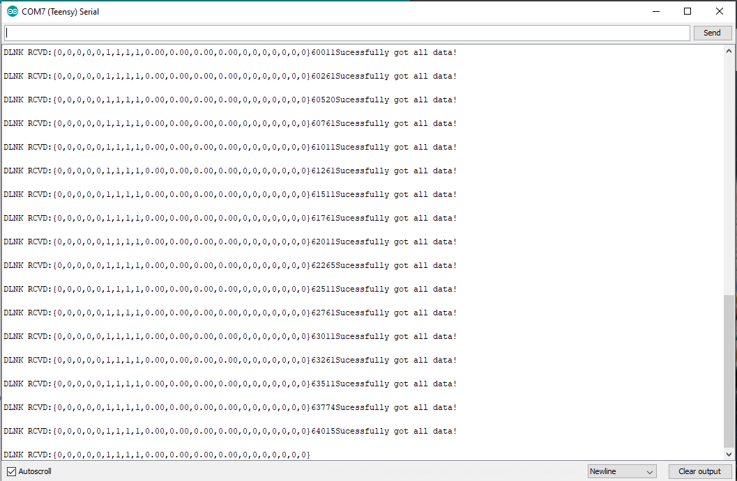
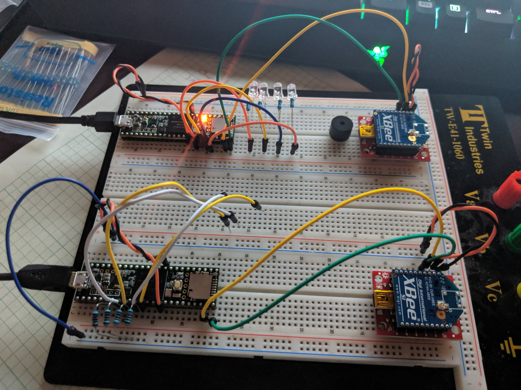
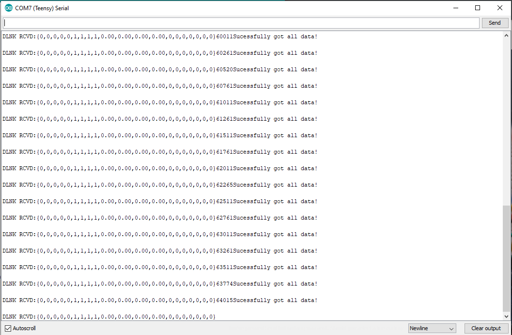
I started by creating a breadboard layout of what I am trying to do with the XBEEs (Xbee s1)...
I started by creating a breadboard layout of what I am trying to do with the XBEEs (Xbee s1)...
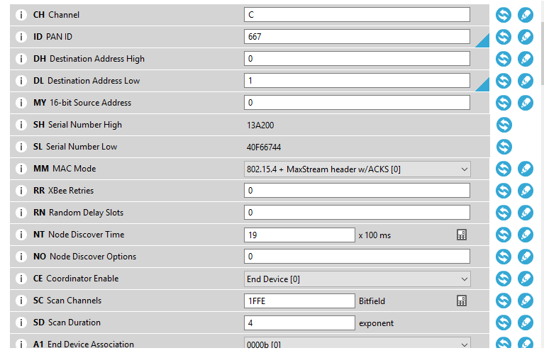
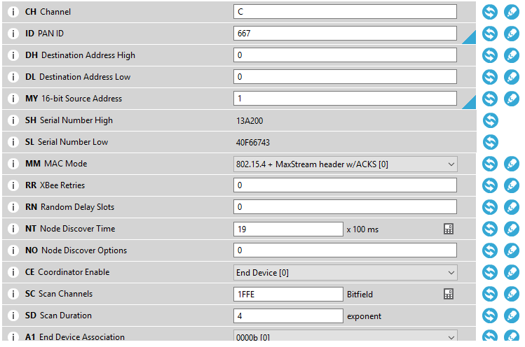
Xbee s1 Config Setup:
Quasar DAQ Junction box Side Code
Code Editor
Quasar Control Board Side Code
Design Phase
I will begin by laying out my electrical Designs for controlling and acquiring data.
I will begin by laying out my electrical Designs for controlling and acquiring data.
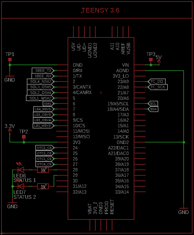
- Main Computer:
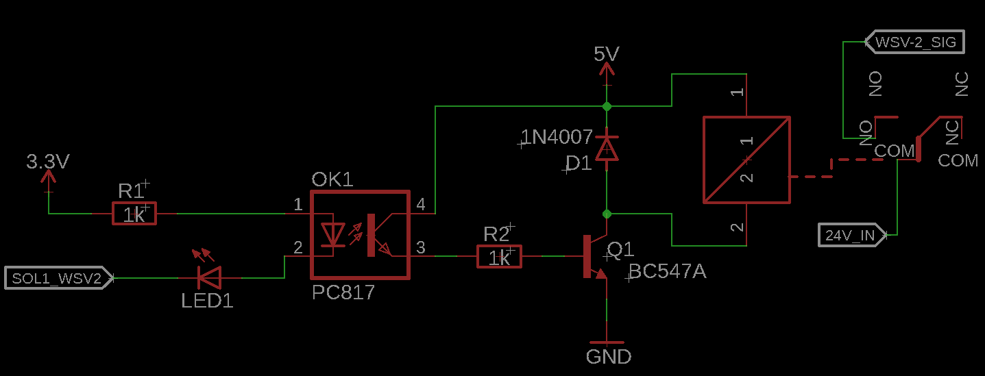
- Isolated Solenoid Relay outputs:
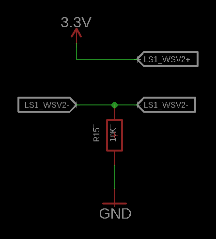
- Limit Switches inputs:
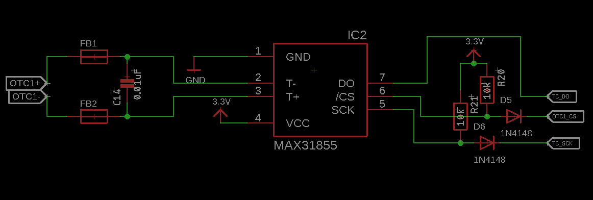
- Thermocouple inputs:
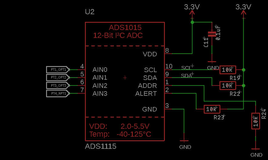
- Pressure Transducer inputs:
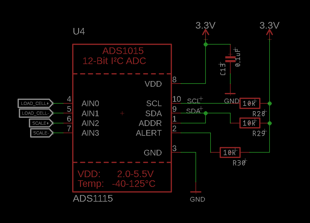
- Load Cell inputs:
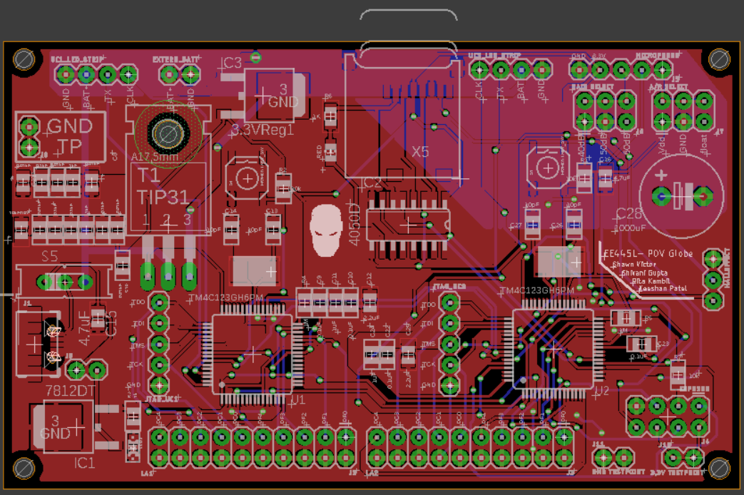
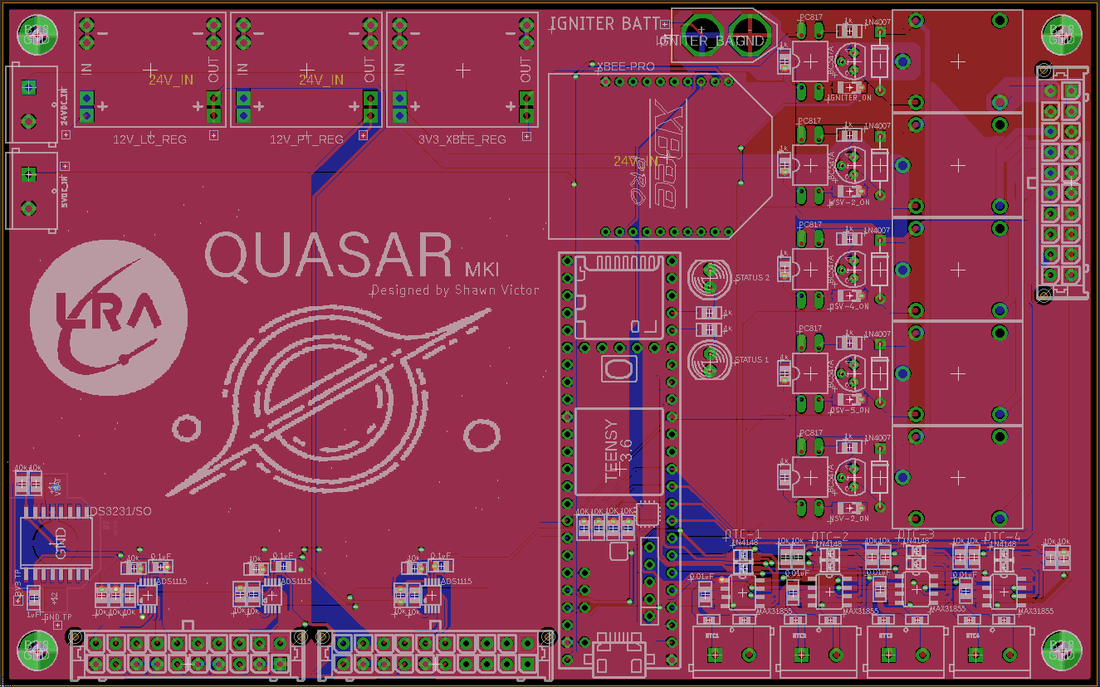
- Board Layout:
