Printed Circuit Boards (PCBs) are an essential part of almost all commercial systems, and thus are an extremely useful skill to master. Getting a hang of PCB design can take a bit of time, but the more boards you design the better you become. Learning PCB design can seem pointless if you don't yet posses the understanding of basic electrical engineering. So I would really recommend checking out my Electronics Fundamentals tutorial series first. I will sort of expect you to know what a resistor, capacitor, and inductor are.
Autodesk Eagle is a robust PCB CAD software that provides users the ability to create electrical schematics and using its large library of components will map each of those components to their physical layout. Let's first go ahead and get some terminology out of they way to avoid confusion!
Autodesk Eagle is a robust PCB CAD software that provides users the ability to create electrical schematics and using its large library of components will map each of those components to their physical layout. Let's first go ahead and get some terminology out of they way to avoid confusion!
PCB Lingo
- What is a schematic?
- A schematic is an electrical blueprint of how a system is connected. It utilizes symbols that represent specific electrical components. These components are then allowed to be connected to one another per the user's desires
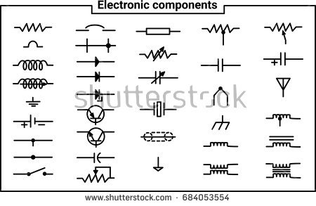
Here is an example of what symbols look like:
|
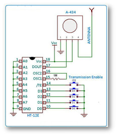
Here is an example of what a schematic might look like:
|
- What is a board layout?
- A board layout contains the physical "footprints" or packages that would allow that specific component to be soldered directly to the board, the board layout allows you to decide upon the position of each of the components as well as creating the specific copper traces that will connect certain components together based on what was specified from the schematic
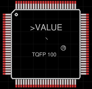
Here is an example of a footprint/package
|
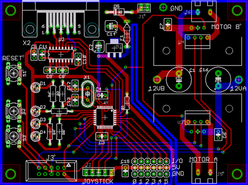
Here is an example of a board layout
|
So what is so special about PCB CAD software?
- Eagle like most PCB CAD software is made up of multiple libraries, these libraries hold repositories of multiple components mapped with their corresponding symbol and footprints. We call the combination of the symbol and footprint a "device". So libraries are just made up of a bunch of devices.
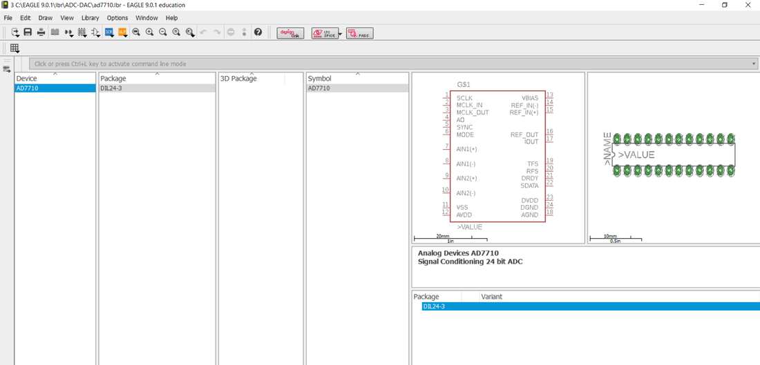
You can see how a library is made up of a list of devices which are mapped to specific package(footprints), symbols, and even 3D packages for 3D rendering PCB Boards!
Getting Started with Autodesk Eagle
Step 1: Download Autodesk Eagle
- Go to the following link: eagle.autodesk.com/eagle/software-versions
- Click on the following link corresponding to you Operating System, you may have to create an account if you haven't already
- Follow the setup instructions until the end
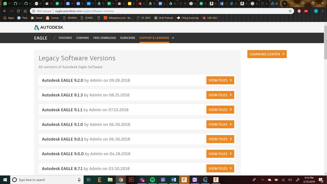
For the purposes of this tutorial series I will be using Eagle 9.0.1, be sure to download this one since the layout of the software past this version is vastly different from the layout I will be using. The guys at Autodesk decided to completely change to layout of the tool bar in version >=9.1.0 :(

Once downloaded, run the .exe file and go through the installation process. It should be pretty simple.
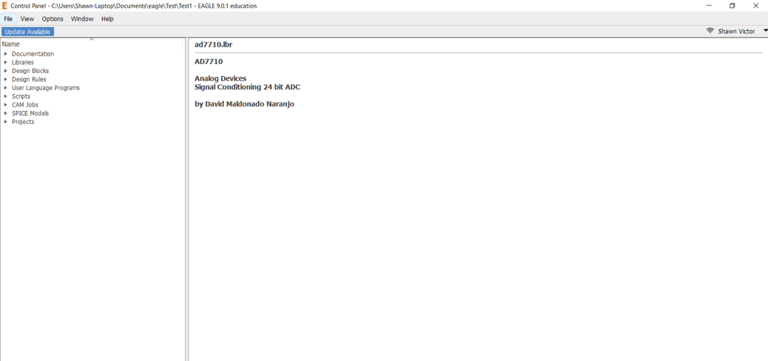
Step 2: Open up Autodesk Eagle
- When opening up the software you may be asked if you would like to update the software. DO NOT update to a newer version, it will make it difficult to follow what I teach in this tutorial
- You should then be directed to a window known as the control panel. The control panel is a window that you can use to browse to eagle related folders/projects. It is here where you will be opening/creating eagle projects.
Opening up the Control Panel Window
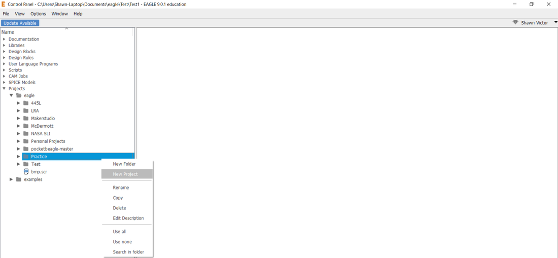
- Let's go ahead and create our first project. In the control panel you will see a drop down option for the Projects tab. It is here where I recommend you create a folder that you can use to categorize your projects into groups. For example, in my Projects tab I have folders for Personal Projects, Research, Specific Classes, ect. Some people chose to create eagle projects directly in this tab, but trust me once you start using this software enough times it will get cluttered really quickly. For the sake of this tutorial, right click on Projects and select New Folder, let's create a folder titled "Practice"
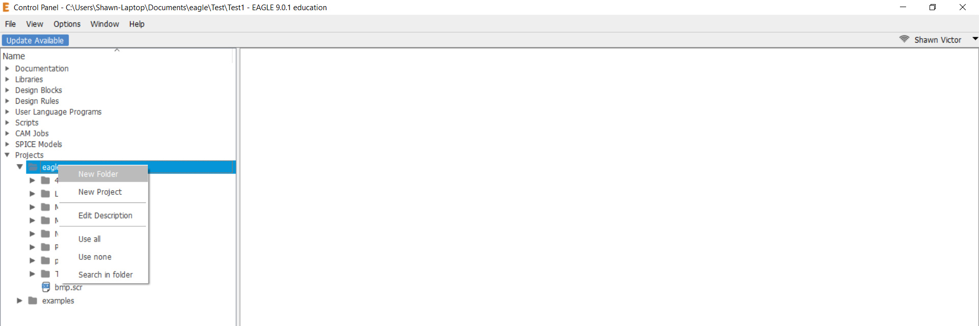
Creating a new Folder
- Now that we have created the Practice Folder, let's go ahead and create an Eagle Project within this new Folder. To do this simply right click on the folder and select New Project, and let's title it "My First Project"
Creating a New Project
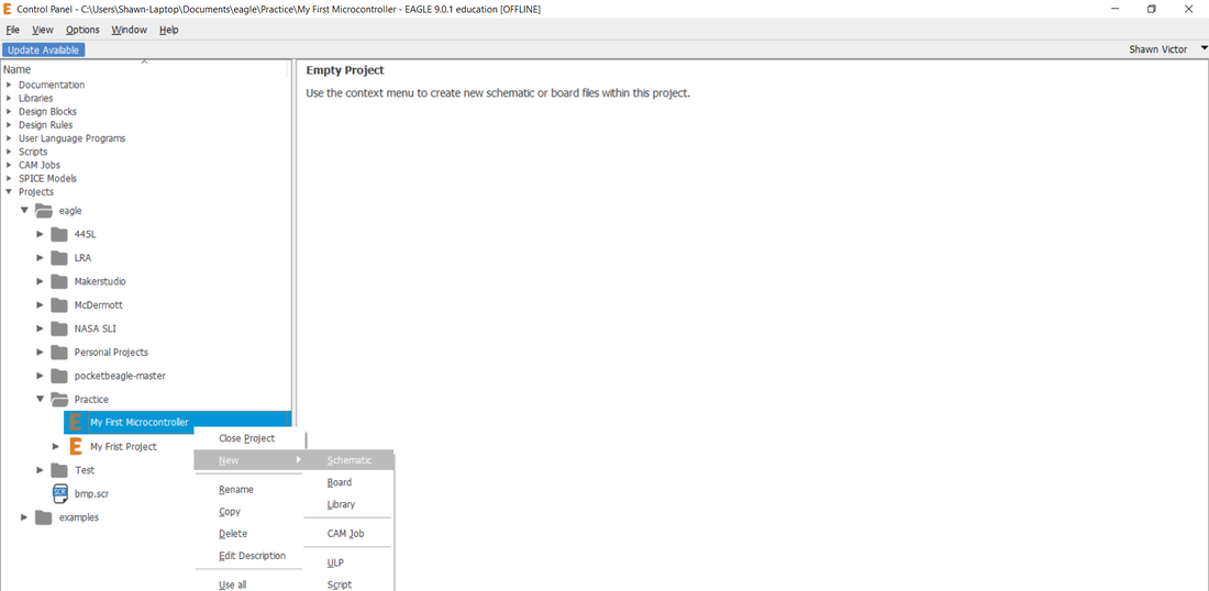
- Once we have created the Eagle Project we can now create new items within this project File. Specifically, we are gonna want to first create a schematic so we can first layout our design. So go ahead and right click on the new Project created and select New>Schematic.
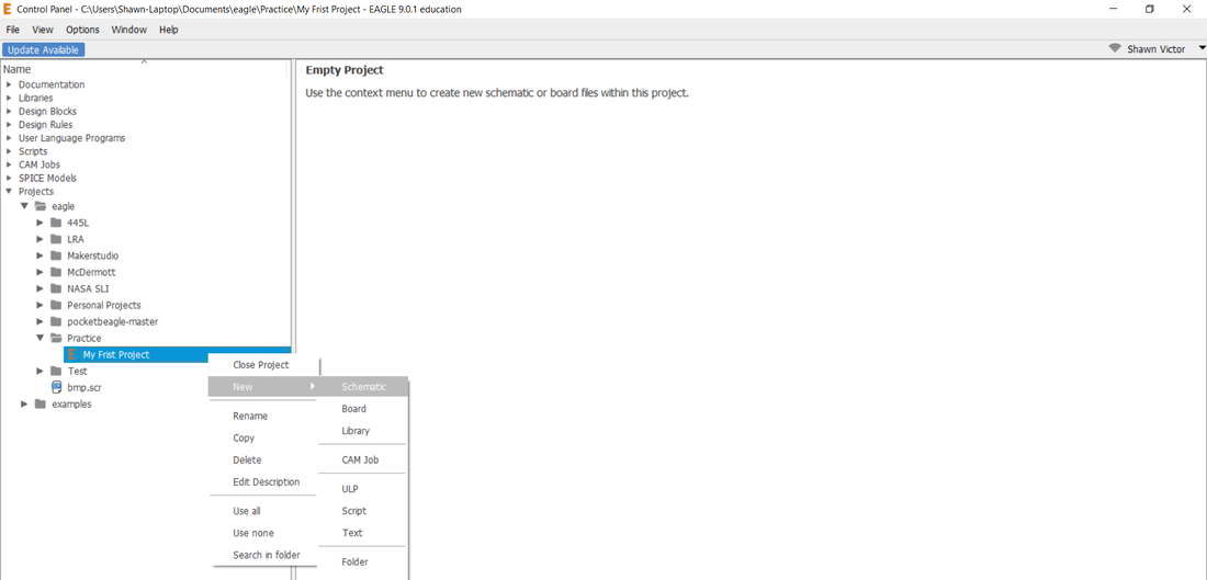
Creating a New Schematic
Step 3: Setting up our Schematic Environment
- Once you have created the schematic Eagle should have created a new window known as the Schematic Window. It is in this window that we will be connecting symbols together as per the way we want them to be connected.
- However, before we can really get started it is important to note that Eagle by default does not contain a lot of common libraries by default, and they need to be manually added in. Fortunately for you all, I have been collecting a ton of libraries over the years of using this software and am willing to share it with all of you. Please go ahead and download the following zip file:
| eaglelib1-22-19.zip |
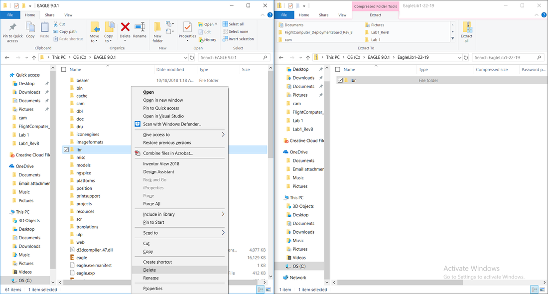
- Once you have the file downloaded go ahead and open it. We need to replace your current lbr folder with this new one with a ton of libraries in it. So go ahead and delete the folder title "lbr" that should be located in C:\EAGLE 9.0.1 . Now go ahead and replace that folder with this lbr folder that you just unzipped from the download.
- Alright, once you have put the new lbr folder in the correct location we can proceed with loading these new libraries into Eagle.
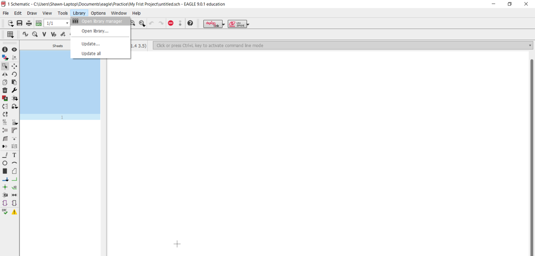
- With the Schematic window open, at the top click Library>Open Library Manager
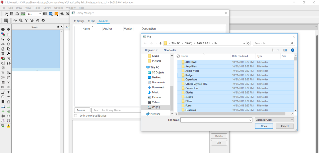
- A new window title Library Manager should have opened, at the top of this window click the tab titled Available. Then towards the middle of the screen should be a button titled "Browse..." select that and a File Explorer should open for you to select the new libraries you would like to add. Go ahead and single click once on one of the folders, then press Ctrl+A to select all files in the lbr folder, then hit Open.
- Once you do this, you should end up back at the available tab with a new list of new libraries listed out. Go ahead and single click one of those libraries and then press Ctrl+A to select all of the libraries listed. Then hit the Use button. Do not be surprised if this almost crashes the program since there a ton of new directories to be added in and it may take a while. By the end of it everything should be loaded in and there should be nothing left in the list anymore. You can then exit this window.
Step 3: Creating our Schematic
- So just to practice we will do a pretty simple layout, then move on to a bit more complex layout.
- We will go ahead and create a flashlight layout. This layout will consist of a coin cell battery, current limiting resistor, button, and LED.
- Let's go ahead and jump back into the schematic window. I should probably start to get you very familiar with Eagle's schematic interface. But in order to do that we will need to first get some devices added to our schematic.
- The first thing I always tell my students to add in first is a frame. This will provide a means keeping a visual bounds for our project, as well as making it easy to print this schematic with proper documentation. To do this we will need to use the add button.

|
This is the Add Button, it is used to add new Devices into the current schematic.
|
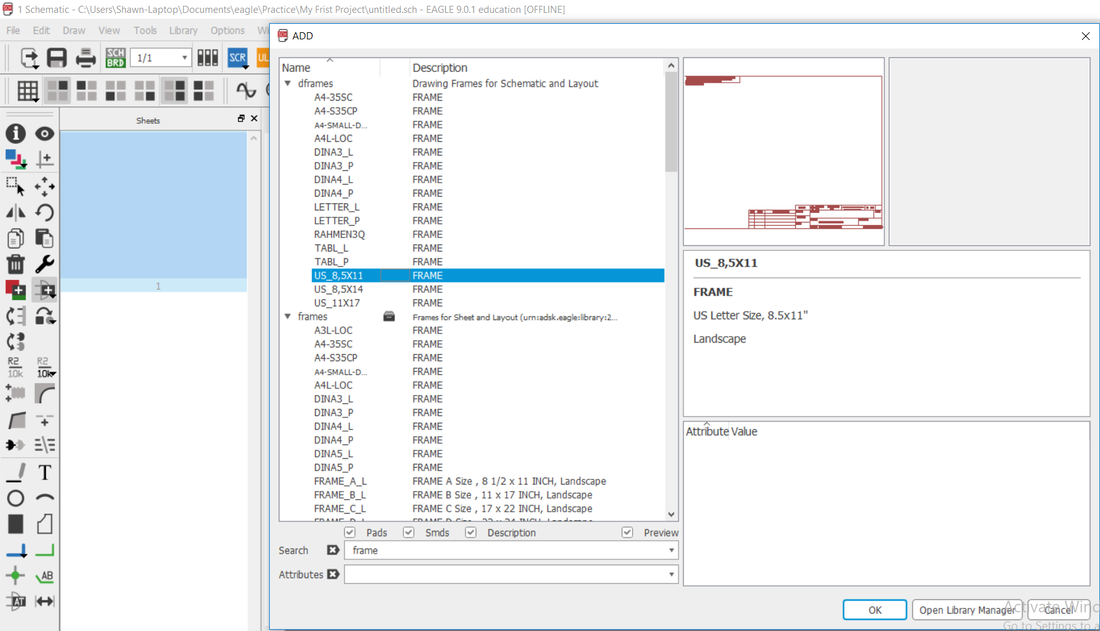
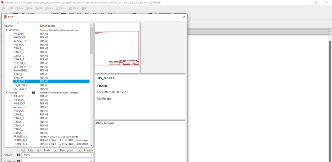
- Using this button we will be able to add in a frame. Simply type "frame" into the search bar and hit enter. You should see something similar, if not scroll down until you see this. The library titled dframes is great for printer size page layouts so your schematic is ready to be printed easily.
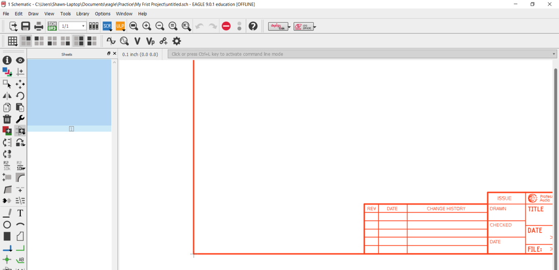
- Once you hit the OK button, Eagle will then allow you to chose the position you want to place the device down on the schematic. Simply click once to place it down. However, you will notice that once hit click once it will be placed down, but the frame will still be in your hand, the reason for this is because Eagle want to hit enter when you are done placing multiple components. This is because it would be really annoying if you had to put down multiple of a specific component by had to select it over and over gain.
- Once you hit escape, you the Add window should be popped up again, this is so you can easily add all of your components in succession. You can exit it out of it for now as we cover how to move devices in Eagle.
- When interacting with any device in Eagle, you first need to understand the most fundamental thing in Eagle, and it is this thing:
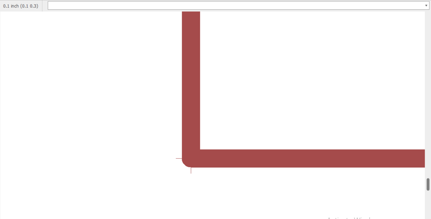
That right there is what we call the Origin of a device. You MUST be clicking right on that cross hair in order to interact with it, whether that be to move it, rotate it, or mirror it. Now let's go through the list of tool bar buttons.

|
This is the Info Tool. If you click on a device with this button selected a window will pop up with that components information/properties which you can modify directly.
|

|
This is the Show Tool. It is very helpful for highlighting the location of devices with the same name but are in separate parts are you will see later. This is helpful if we know the name of a component we need to find but don't know where it is located.
|

|
This is the Layer Tool. We can use it to toggle the visibility of certain layers in Eagle. We will get into Layers a bit later.
|

|
This is the Mark Tool. It is helpful in marking a temporary position of something before you move it to another location.
|

|
This is the Group Select Tool. It is helpful for moving multiple devices at the same time. Simply select this tool, drag select a box around the components you want to move then while click holding the cross hairs of once of the components you want to move you can start moving the group of components
|

|
This is the Move Tool. It will be the most used tool since it allows you to move the position of a single device
|

|
This is the Mirror Tool. It is helpful for horizontally mirroring a symbol or moving a package to the opposite layer in the board layout window
|

|
This is the Rotate Tool. It is used to rotate any symbol or package by 90 degrees every time you click on the cross hairs of that specific device
|

|
This is the Copy Tool. You can use it by clicking on the cross hairs of any device and it will automatically create a duplicate of that device in your hand to place down on the schematic.
|

|
This is the Paste Tool. It works in correspondence with he Copy Tool since it remembers the last thing that was copied and keeps it in a buffer, when this tool is selected it will place that last copied item in your hand for placement onto the schematic.
|

|
This is the Delete Tool. You will be using this frequently to remove/delete components from your schematic.
|
Now that you understand these fundamental tools we can now start to actually finish up our schematic!
Practicing Our Schematic Skills
This can definitely be the most daunting part for beginners who don't have too much experience with designing circuits. However, it is hard to get good at this skill without a bunch of practice(aka keep trying to design them). While I could spend all my time teaching you the essentials of circuits it would be way to time consuming(you can always check out my Electronics Fundamentals section for more info on that sort of knowledge). Rather, I will spend most of my time guiding you towards designing your own micro controller from scratch.
Instead of having you add a bunch of components in and have you connect everything up, I will instead provide you the whole schematic in the form of a design block. But first, we should first cover what a design block is. A design block essentially allows you to save chunks of your circuit diagram for later use. You will find that once you are finished creating large circuits networks it can be a pain to spend time recreating the circuit again in another project. Instead, what Eagle allows you to do as save chucks of your circuit as a design block for later use. This will save you a lot of time and pain.

|
This is the Add Design Block tool to add in saved Design Blocks into your schematic or board layout.
|
Before we can use this tool to add in our design block we first need to add in my design block for the Arduino Nano. This design block contains all the bare bones hardware required to use this mircocontroller. The specific chip that the Arduino Nano uses is the ATMEGA328P-AU, the AU part signifies that the microcontroller is in a surface mount package size. If surface mount is a new term to you, just wait till later on to see what I mean by that.
Step #1: Download and Add in the Design Block
| barebones_arduino_nano_dbl.zip |
| esp32-devkitc-32d.zip |
- Start by downloading the file above. This is the design block file that you will now be able to start adding the ATMEGA328P microcontroller to your projects.
- Copy and Paste the File into the following File Location: C:\EAGLE 9.0.1\dbl n
- Now create a new Eagle Project named "My First Microcontroller" and then create a new schematic within it.
- Now go ahead and add in a new Frame from the dFrames library. The US_8.5X11 is a good size frame! And place one down right on the origin of the sheet you are in.
- Next, we will use the Add Design Block tool to add in a new Design Block. This should open up a new Window and we should be able to find that new file we added in: ShawnsNano. Click the down triangle button until you see a line named Sheet:1 , double click this.
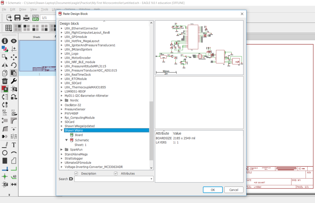
- Now just place down the design block into the frame.
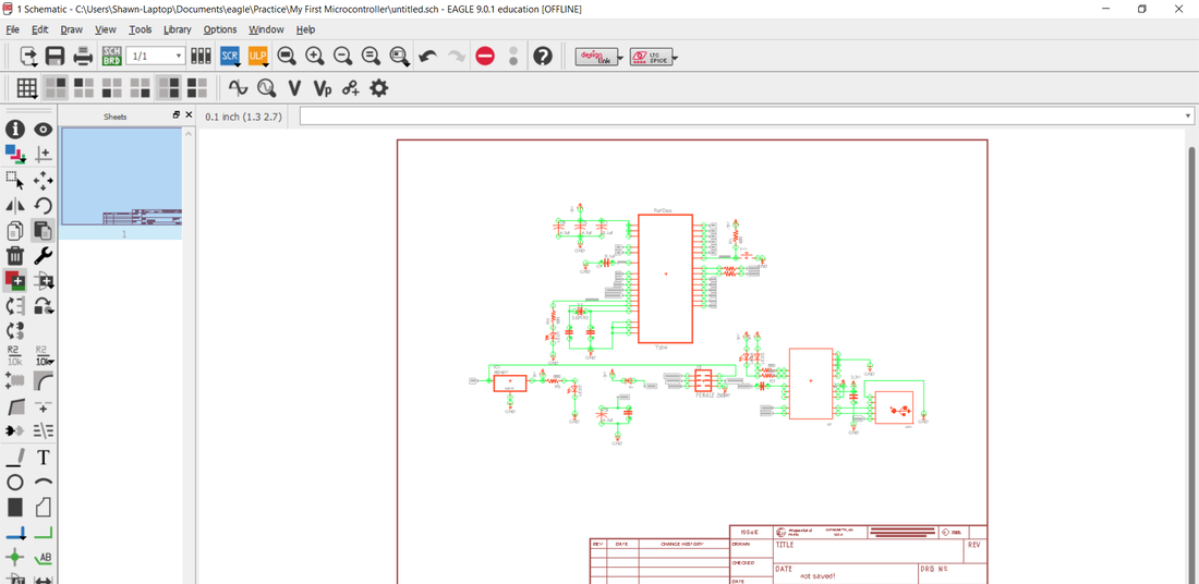
Let's go ahead and talk about the specific parts of this schematic. Simply using a schematic without proper understanding of the specific parts is a recipe for circuits that don't work.
Microcontroller Standalone Electronics
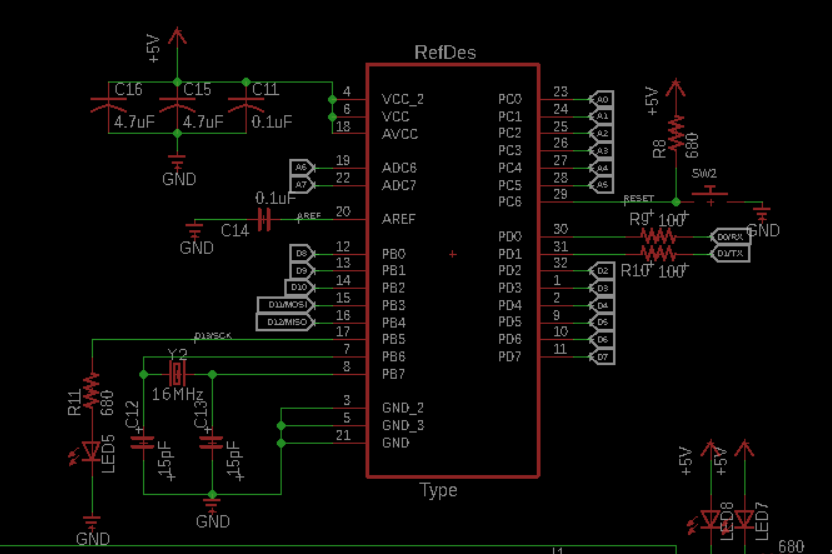
So let's first look at this part of the circuit. This large rectangular symbol is the microcontoller symbol. For those of you who don't know much about microcontrollers we can for the time being just think of it as the programmable brain of our circuit. All other electronic symbols in this diagram are there to support this microcontroller, so that it will be able to function properly. We are now gonna cover each of these support electronics and how they play their own important role in allowing the microcontroller IC function properly.
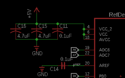
The first thing we need to discuss is VCC or Voltage Common Collector. Vcc is common terminology for CMOS based devices that are made up of a complex array of MOSFETS within the micocontroller. It is important that we keep the Vcc lines as clean (we can the DC voltage to be as close to a flat line as possible), any ripples in the voltage lines can cascade more noise to the whole system and put it out of normal operation. Now a common question that is asked is how we came up with these seemingly random capacitor values, and why are some of the capacitors we use polarized capacitors vs. Non-polarized capacitors? To explain that concept might take some time over text, so I recommend you take a look at this video here done by Youtube Electrical Engineer Dave. It's kind of long, but covers all the details needed to understand where these values come from, and why they are so significant.