Custom Flight Computer Mk.II
This project was started to stray away from utilizing commercial flight computers as Longhorn Rocketry's only means of logging launch data. The issue with designing a custom flight computer system really comes down to rigorous amounts of testing required to certify the computer works reliably and consistently. Specifically, this would require massive amounts of time and money to hold multiple launches to test our system. Since this flight computer was designed to support all certification rockets as well as for our flight computer in the Spaceport America Cup(SAC), I made sure to abide clearly to the regulations provided by SAC.
Spaceport America Cup Flight Computer Regulations
- For official reporting of the altitude, a Commercial Off the Shelf (COTS) Flight Computer must be present on the rocket
- Telemetry can be used as a means of official reporting, but it must receive data from the COTS flight computer
Certification Rocketry Regulations
- In order for a custom flight computer to act as the main computer of the rocket, it must have at least 10 successful launches as a secondary computer
- A COTS Flight Computer is ALWAYS required on the system as an extra measure of redundancy
Initial Layout
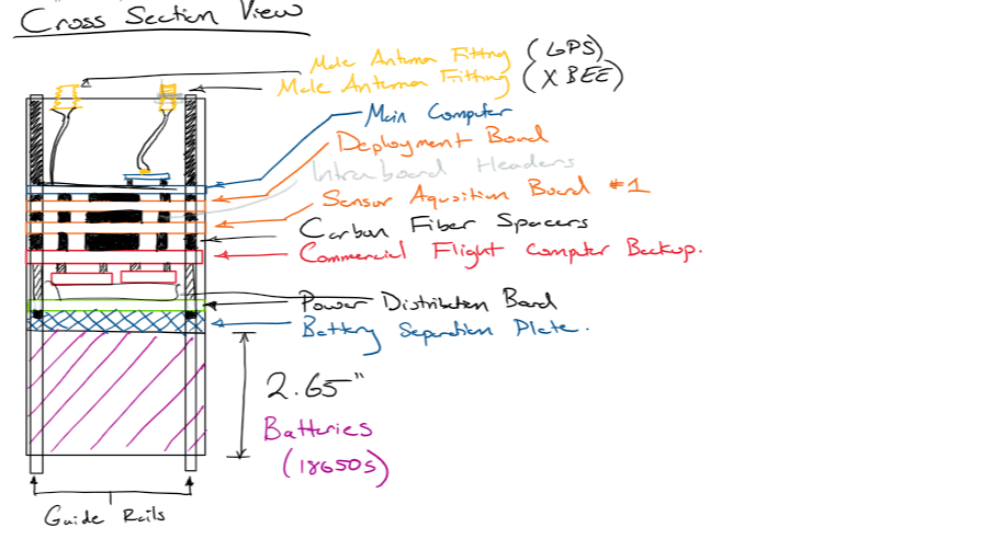
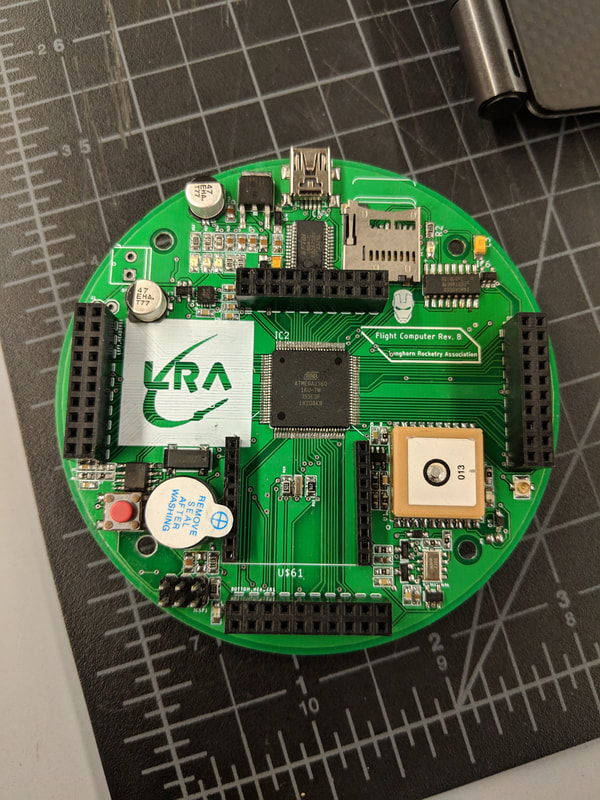
The way I went about designing the internals of the electronics coupler was to go with a "Wedding Cake" style in which each board would be 3.65" in diameter, and using male/female headers we could essentially stack these boards on top of each other. The boards may not be as rigidly held together if just using headers, so we will also use metal standoffs to sandwich these boards together. This version of the flight computer is designed around to support a hybrid rocket engine with abilities to actuate an air braking system, thus there are four other boards apart from the main board. The main board can be used alone on COTS rockets to log data, but since this system is so versatile I can design boards to stack on this board for extra features. So in total there are 5 boards that will interface with each other. I will be addressing each board by the following names: Main Board, Deployment/Air Braking Board, Auxiliary Sensor Board #1, Engine Sensor Board, Power Distribution Board.
Main Board Requirements:
- Handles all sensor Data Acquisition, Data Storage, and Telemetry
- High G Accelerometer
- Altitude, Pressure, and Temperature Sensors
- 9-DOF Inertial Measurement Unit
- Global Position System (GPS)
- Long Range RF Transceiver (XBEE)
- SD Card External Storage
- Buzzer system
Deployment Board/Air Brake Board Requirements:
- This board has the functionality of igniting black powder charges, driving the air brake motor, and reading the motor encoder
- Ability to drive High Torque Servo Motor
- Nominal Voltage: 7.4 Volts
- Max Stall Current: 4 Amps
- Work Time: < 20 seconds
- Independent Pressure, Altitude, and Temperature Sensor
- Independent Acceleration/IMU Sensor
- Ability to get Altitude data from COTS Altimeter
- Ability to know when Motor has ignited and when parachutes are deployed
- Ability to drive High Torque Servo Motor
Auxiliary Sensor Board #1 Requirements:
- This board acts as a dedicated board purely to get more data that can be post processed for later analysis
- Piedo Tube Sensor for Rocket Velocity Data
- SMS module for sending data across phone
- Ect. More to think of....
Engine Sensor Board Requirements:
- This board has the functionality of logging key engine data including pressure readings, valve actuation, and temperature data
- 3 Channel 16-bit ADC
- 2 Channel K-Type Thermocouple Sensor
- 4 Relays for Solenoid Actuation
- 4 Corresponding Limit Switches for the Solenoids
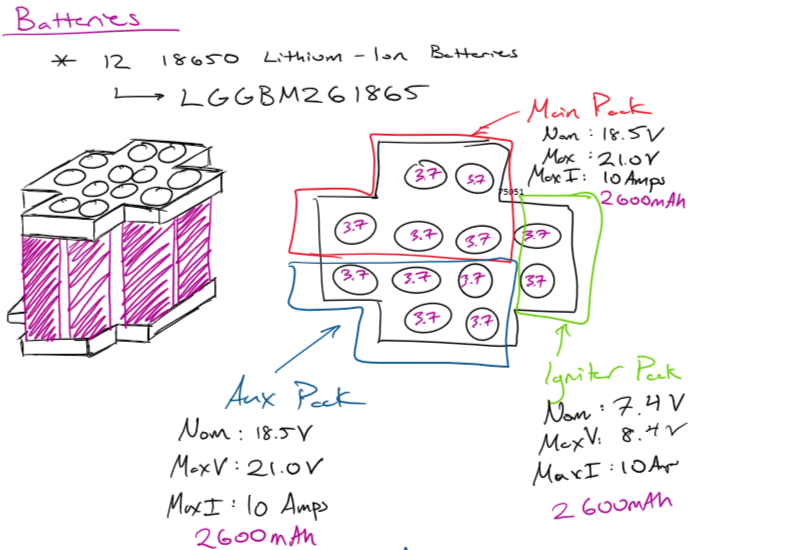
Power Distribution Board Requirements:
- This board provides a regulated low noise supply for each of the boards, also has high discharge capabilities to drive motors and igniter
- Battery Management System(BMS) to prevent damaging of the cells, over-discharge/under-charge protection, short circuit protection
- Needs to be able to switch battery packs mid flight, if the main pack disconnects or becomes undercharged, there needs to be no significant voltage drop once the switch occurs
- Recharging Capabilities for the cells to be recharged
CAD
Design
Main Board Design:
Deployment/Air Brake Board Design:
Sensor Board #1 Design:
Due 1.30.2019
Due 1.30.2019
Engine Sensor Board Design:
Due 1.30.2019
Due 1.30.2019
Power Distribution Board Design:
Due 1.30.2019
Due 1.30.2019